RV Cycloidal Reducer
Working Design
I mostly designed this gearbox for the fun of it, however the driving dimensions and loads for the reducer are based on the requirements of Cornell Mars Rovers’ wheels and 6 degree of freedom robotic arm.
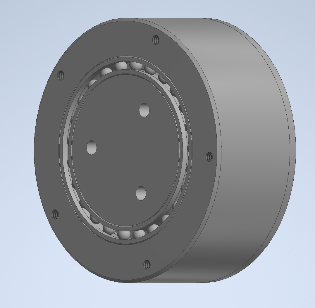
The gearbox is specifically a RV (radial vector) reducer. In essence, an RV Reducer is basically part planetary gearbox, and part cycloidal gearbox. The major benefit an RV Reducer has over either type of gearbox in isolation is that it minimizes the major drawbacks of planetary and cycloidal drives. Having a planetary stage before a cycloidal stage helps the gearbox start and overcome initial sticking of the cycloidal disc. The planetary stage also increases the number of input shafts from one to three, which increases the load capacity of the system by spreading the transmitted torque through all three input shafts. A cycloidal stage after a planetary stage reduces the amount of backlash inherit in spur gears by the reduction in the cycloidal stage (in this case 25:1). The cycloidal stage also has an extremely high torque density and zero backlash, allowing for high reductions and very little backlash.
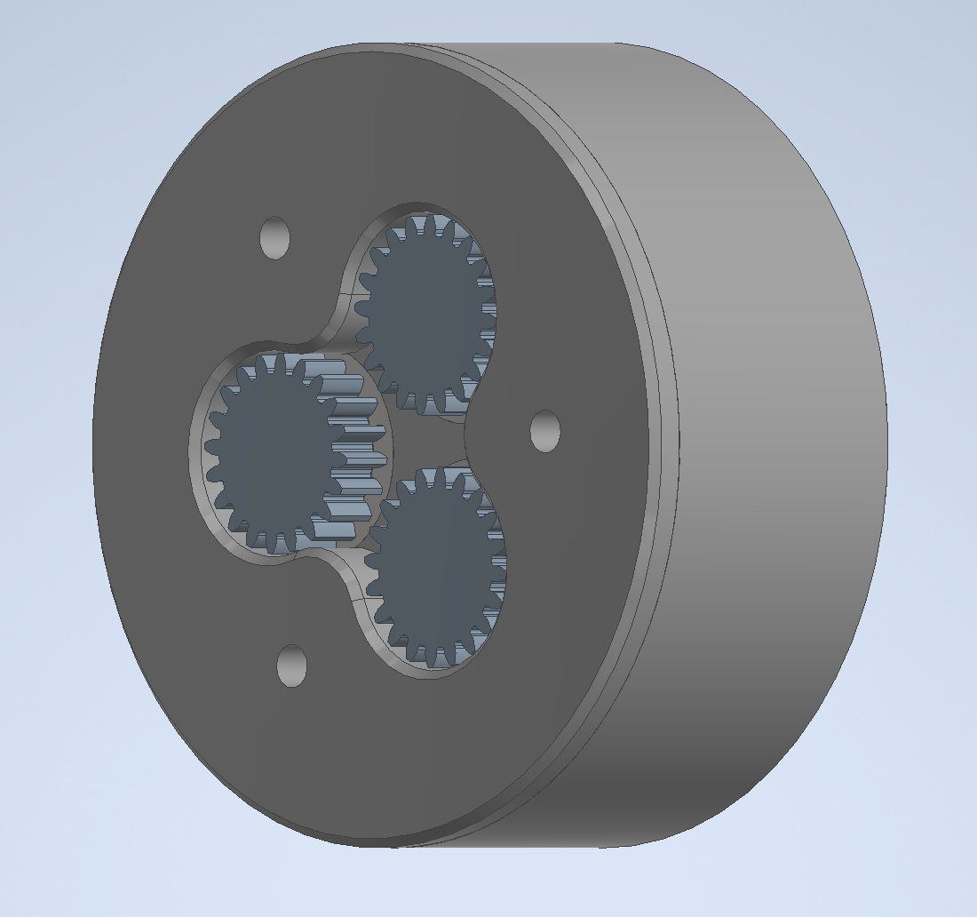
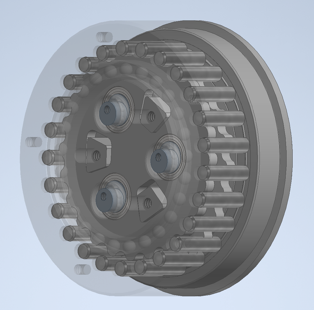
The input for the gearing, pictured top left, uses 3 spur gears, which are driven by a sun pinon connected to the driving motor. Each of the planet gears spin an eccentric shaft, pictured blue in the bottom, which drives the eccentric wobble of the cycloidal discs. The two cycloidal discs spin 180 degrees out of phase, which negates the linear vibrations that would be present in a single disc system but introduces a rotational vibration which is easier to compensate for. The discs wobble around the three stationary trapezoids, which causes the output disc to rotate. The overall reduction of the system is 50:1, while only having a diameter of only 2.75'“ and a length of 1.25”.
Internals
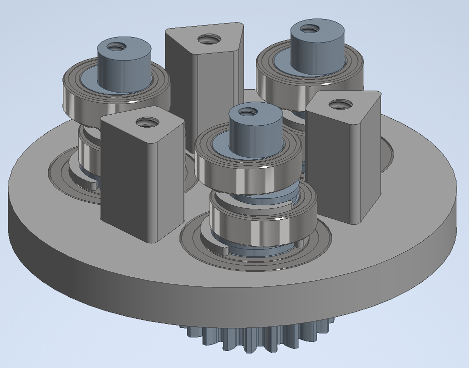
Pictured left is the gearbox input assembly. The driving dimensions for the eccentricity, bearings, and gear spacing are all derived from off the shelf availability of bearings and spur-gear stock. The dimensions of the trapezoids are based off the diameter of the circle they inscribe, which is prescribed in Rao’s ”Planetary transmission mechanism design” 1994 research paper. The purpose of using trapezoids over other shapes is to have a larger constant contact area, and thus larger torque capacity.
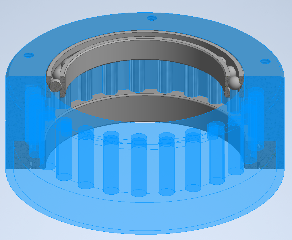
Pictured right is the output disc (blue) and the two bearings that it rides in. The output disc is made of 6061 aluminum and has 4140 steel dowel pins press fit around the inner diameter to mesh with the 4140 steel cycloidal disc. The purpose of having two bearings is to help the gearbox resist applied moments applied to the gearbox so that the gearbox casing can double as a structural component.
The cycloidal disc is designed with ease of manufacturing in mind. It is made of a single extrusion so that it can be cut easily on a water-jet or plasma cutter with a high degree of accuracy.
Master Sketch
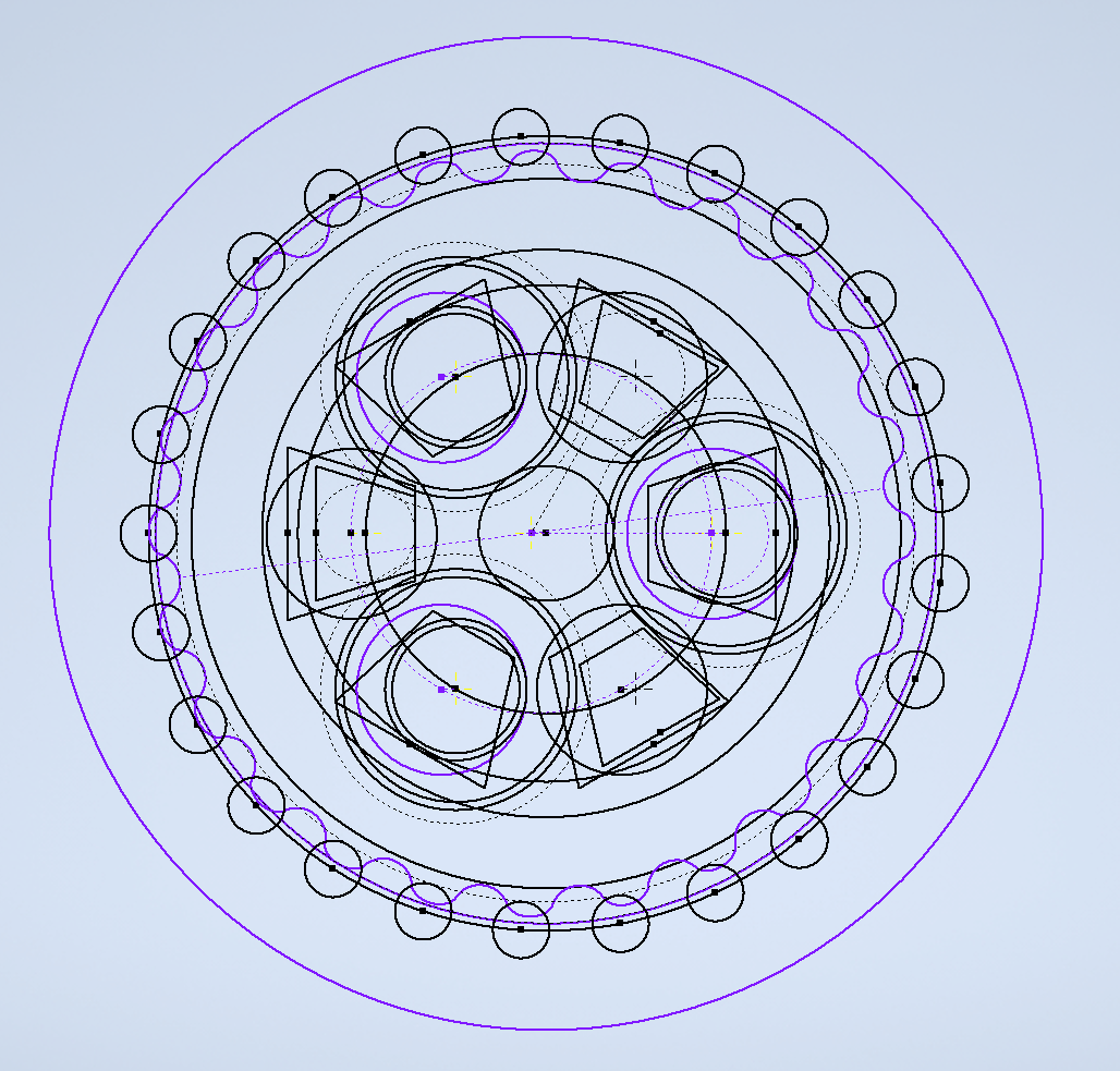
The whole gearbox is based off a single top-level sketch that has all the dimensions and relations. This allows for different reductions and dimensions to be inputted into a spreadsheet and all non off the shelf geometry to update accordingly. For example, if for a given application a higher reduction is required, all the needs to be changed is the reduction ratio in the spreadsheet for the whole gearbox assembly to update to that ratio.
