Functionality
The swerve module’s primary function is the independent turning of all four wheels of the Mars Rover. In all past iterations of the rover “tank drive” has been used. In a tank drive set-up, the left and right side wheels are operated at different velocities to move forward/backwards, swing turn, and point turn. In practice, this does not work well. Driving straight is easy with tank drive. Swing turns, especially with tight turning radii desired, are extremely difficult. Point turns with tank drive is next to impossible. This means that fine positioning of the system for certain competition tasks is unachievable. The implementation of swerve modules to the system should alleviate all these problems.
Swerve modules will allow the rover to move omnidirectionally. Putting all four wheels at the same angle will allow the rover to drive in the direction of the wheels, independent of the heading of the rover. This translates to the rover moving in any desired vx , vy velocities. By turning the wheels to angles that are tangent to the circumference of an imaginary circle that they lie on, the rover will be able to point turn. This translates to the rover rotating at a desired roll rate. Using a combination vx , vy, ωz, the rover should be able to drive in any direction with any amount of roll simultaneously.
Performance Objectives
Design
This design uses a 100:1 Laiful Drive harmonic gearbox and Maxon EC-60 brushless motor. Harmonic gearboxes are a good choice for high dynamic load applications because they are designed specifically for robotic actuators. They come with cross-roller bearings on the output of the gearbox, which effectively transmits radial, axial, and moment loading to the casing of the gearbox rather than the internals. Harmonic drives are also a good choice because they have zero backlash. Although not as important for this system as it is for something like a robotic arm, zero backlash will ensure that the wheel angle is known with 100% certainty at all times. A brushless motor is used because it can be commanded to a particular angle with relatively high accuracy using a brushless motor controller like the Moteus R4.11 used here. Lastly, a majority of the structural components are laser-cut sheet metal and bent sheet metal. Using bent sheet metal is advantageous because it is extremely cost effective compared to CNC machining, which helps keep the cost down.
Control System Design
The control is based on the user specifying a desired vx , vy, ωz of the system, which are mapped to inputs of a PS5 game controller. The desired vx , vy , mapped to the left stick, is combined with the desired ωz, mapped to the right stick, into an overall wheel angle vector and wheel speed. To develop the control system for the rover, the relationship between wheel angles and speed and the kinematics of the overall system must be derived.
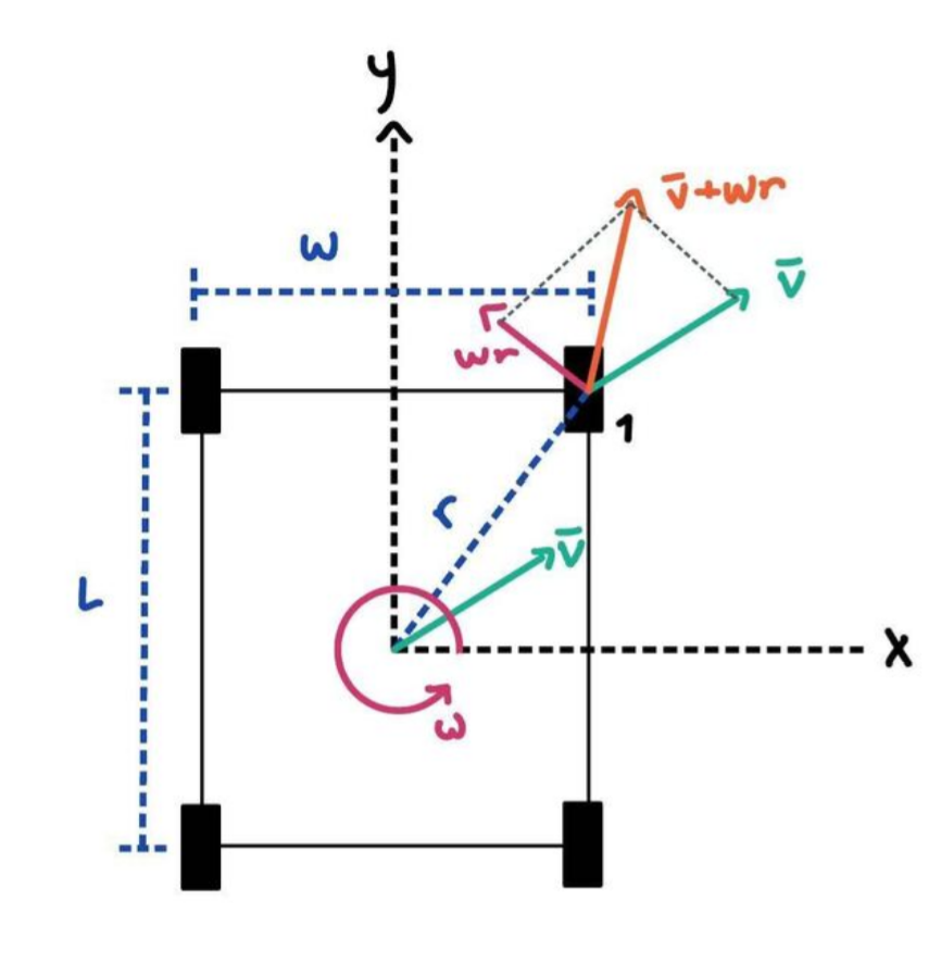
For a given robot velocity v and robot rotation rate ⍵ the speed and angle of a wheel is calculated in the following way. The distance a wheel is from the calculated from the center of the wheel base r, is calculated using:
√(L/2)^2 + (W/2)^2)
The vector the wheel needs to be at to achieve the commanded ⍵ is thus:
⍵r
The vector the wheel needs to translate v is simply:
v
The composite of translation and rotation is just the vector addition of these two vectors:
⍵r+v
Converting this to vector components for wheel 1 gives us:
v1x = vx + w(L/2) and v1y = vy + w(W/2)
The other three wheels follow in the same manner. Going from the above kinematic relation to code, where wheel speeds are normalized such that a wheel speed of 1 indicated the max allowed speed of the system gives us the python function below. We can simulate wheel angles and speeds with this function to give a good ensure everything is working right.
def wheelAnglesAndSpeeds(Vx, Vy, omega, L, W):
    """calculates the wheel angles and speeds for a swerve module

    Args:
        Vx (double): desired velocity in the X direction, as a porportion of the max velocity
        Vy (double): desired velocity in the Y direction, as a porportion of max velocity
        omega (double): desired angular roll rate
        L (double): wheel base length
        W (double): wheel base width
    """
    R = math.sqrt(L**2 + W**2)

    #define helpful variables A-D
    A = Vy - omega * (L/R)
    B = Vy + omega * (L/R)
    C = Vx - omega * (W/R)
    D = Vx + omega * (W/R)

    #define wheel speeds
    ws1 = math.sqrt(B**2 + C**2)
    ws2 = math.sqrt(B**2 + D**2)
    ws3 = math.sqrt(A**2 + D**2)
    ws4 = math.sqrt(A**2 + C**2)

    #define wheel angles
    wa1 = math.atan2(B,C) * 180 / math.pi
    wa2 = math.atan2(B,D) * 180 / math.pi
    wa3 = math.atan2(A,D) * 180 / math.pi
    wa4 = math.atan2(A,C) * 180 / math.pi

    #normalize wheel speeds
    max = ws1
    if(ws2 > max): max = ws2
    if(ws3 > max): max = ws3
    if(ws4 > max): max = ws4
    if(max > 1): ws1 /= max; ws2 /= max; ws3 /= max; ws4 /= max

    ws1 = round(ws1, 2)
    ws2 = round(ws2, 2)
    ws3 = round(ws3, 2)
    ws4 = round(ws4, 2)
    wa1 = round(wa1, 2)
    wa2 = round(wa2, 2)
    wa3 = round(wa3, 2)
    wa4 = round(wa4, 2)

    return(ws1, ws2, ws3, ws4, wa1/360, wa2/360, wa3/360, wa4/360)


