3D Printed Rover Wheels
Current Design
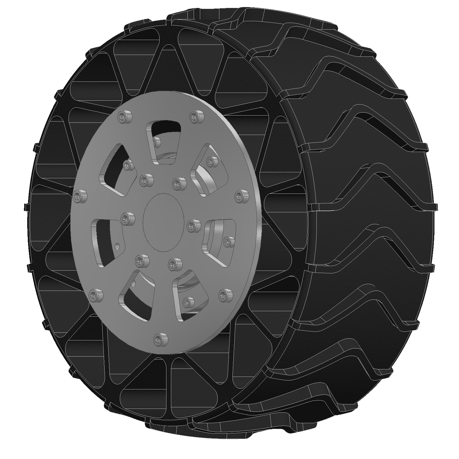
My wheel design for Cornell Mars Rover’s 2023 and 2024 rover is a ground up redesign intended to eliminate major problems associated with our wheels from previous years. This design features a 3D printed TPU tire, which allows us to create more complicated geometry compared to previous tires, while also decreasing the man-hours to manufacture each tire. The hub is a parallel plate sandwich design, which bolts through either side of the rover. The hub is easier to manufacture than previous hubs as it can be done on a water-jet, and connects to the wheel through a mechanical connection instead of an adhesive, making it more reliable.
Problems Addressed and Previous Design
The previous tire was cast Shore 45A polyurethane with a poly-carbonate shear-band in between the treads and the the truss structure. The hub seen bottom left, was two pieces of machined aluminum 6061 epoxied together: the hub face, which bolted to the wheel gearbox, and the hub body, which was epoxied to the tire.
The three main problems with this design was the excessive machining hours required to make a single wheel, and the adhesion problem with the epoxy. The combined tire and hub man hours required to manufacture a single wheel was 11+. Additionally, it was very difficult to manufacture all six wheels uniformly. Almost all wheels exhibited tire hub adhesion problems, pictured bottom right, when mounted on the rover, even before driving.
Previous Iteration Tire Design
The new tire is printed from NinjaTek Chinchilla 75A TPU. 3D printing the tire has two main advantages. 3D printing is able to achieve more complicated geometry than casted polyurethane, and 3D printing is incredibly consistent.
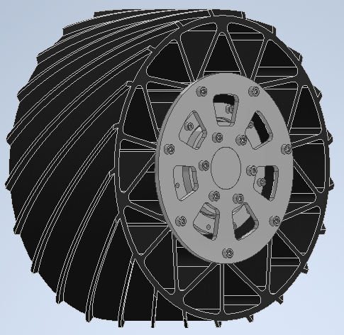
Having the option for more complicated geometry allows for an interlocking tread pattern, which results in a smoother ride and through holes in the tire, which are used to mechanically connect the tire to the hub using aluminum “spokes” bolted to either side of the hub.
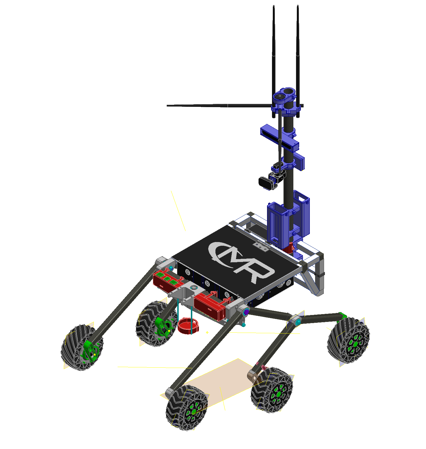
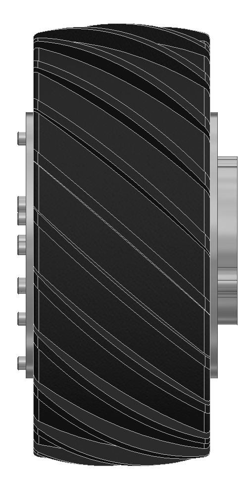
The design of the tire grousers differ depending on where the wheel is located on the rover. Currently, the rover turns like a tank (ie when turning, all wheels on one side of the rover move at a speed different from the wheels on the other side of the rover). Having angled treads on the four corner wheels of the rover results in a smoother turning process because the treads are in line with the turning radius of the rover.
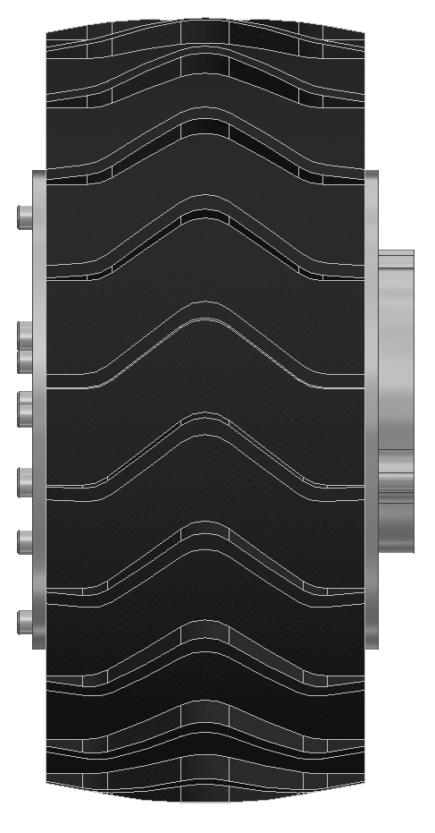
During the testing of the 2023 rover, a problem with my first wheel design, previous wheel designs, and our rocket bogie suspension system came up. The rover had trouble point turning in rough terrain like grass. To fix this problem I added curvature to the outside of the wheel and removed sharp corners on either edge of the wheel because they are prone to dig into the ground when moving laterally during a point turn.
New Tire Design
Stiffening Band
One of the major problems with using mechanical connections instead of an adhesive when connecting the wheel to the hub is that the mechanical connections are not constant around the inner diameter of the tire. This means that the tire only has rigid support from the hub when rolling over one of the seven aluminum spokes connecting either side of the wheel. To fix this problem, a 3D-printed carbon fiber reinforced stiffening band is inserted inside the wheel, to approximate a constant stiffness similar to the previous design.
Magnetic Encoder Mount
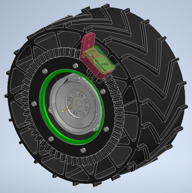
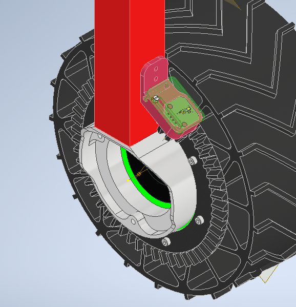
The RPM of the wheel is measured using a magnetic encoder and bevel gear to transfer the wheel's rotation to ninety degrees. My first few iterations of this design had a similar encoder assembly (with spur gears instead of bevel) stuffed inside the wheel assembly; however, every variation of this design added a minimum of .25” to the depth of the wheel, which was unacceptable.
The bevel gear system allows the RPM of the wheel to be measured without negatively impacting the loads the wheel and suspension resist. It also greatly simplifies wiring and repairability, as all the electronics and mechanical connections can be serviced without taking the entire wheel assembly apart.
Wheel Mount
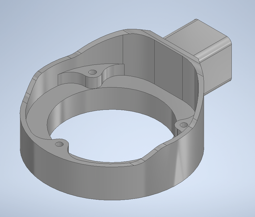
The wheel mount bolts to the back of the gearbox and is epoxied to the suspension. The mount is designed to be compatible with all three suspension mounting locations, to be easily CNC’ed on a 3-axis machine with minimal setups, and for weight.
Validation Testing
Unlike my previous projects, I don’t know any way to mathematically prove my design will work. FEA doesn’t lend itself to infill or 3D prints, and the material properties of the the TPU used for the print is unknown. Instead, to validate the design, the wheels are going through a series of progressive tests before officially being used for the 2022 and 2023 rovers.
The 3D print parameters are currently being refined. Some heat treatment has been tested and confirmed to be useless. A testing rig to load the wheel and drive it over varying geometry is planned but TBD.
Pictured to the right is a qualitative comparison of the stiffness of two min-wheels with different printing parameters.
