E-Core
Current Design
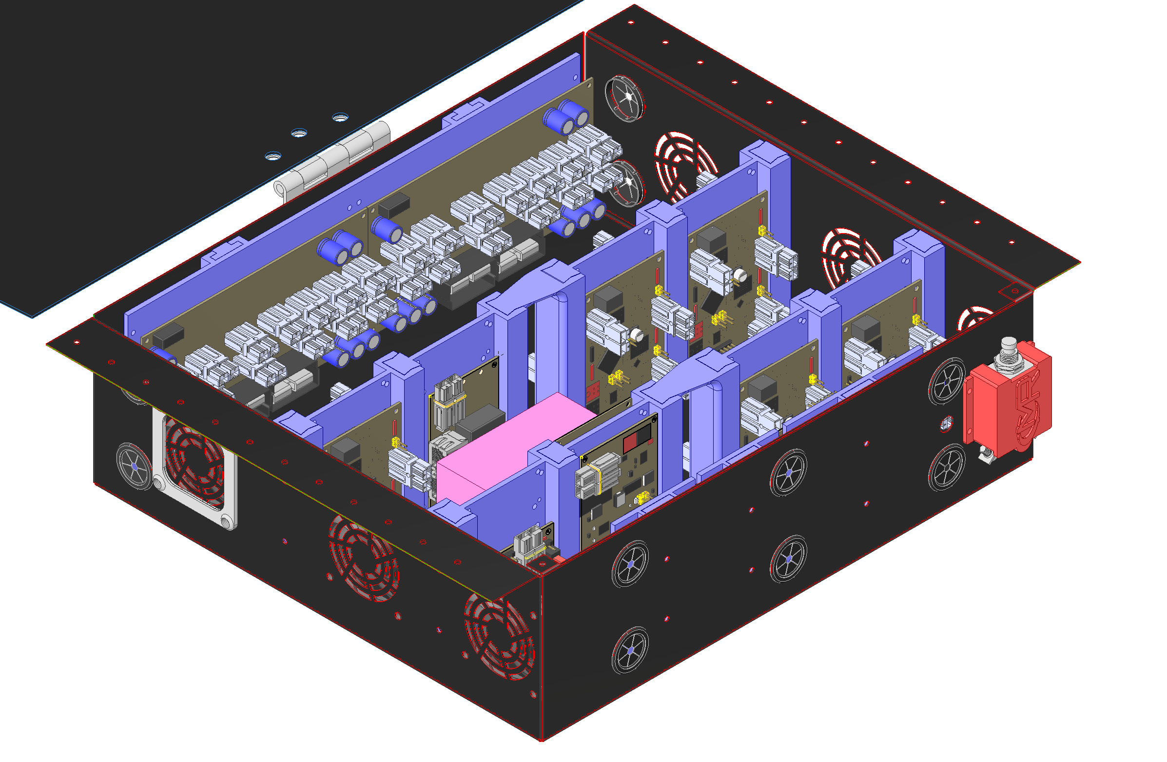
This year the e-core had to fit 22 boards, more than double the amount of boards than in previous years. I also felt it would be valuable to have the system modular for ease of repair and wiring. To accommodate 22 boards, I mounted most of them vertically inside the system on 3D printed universal board mounts. The 3D prints have a universal hole pattern able to accommodate 5 different types of boards and connect to each-other via interlocking dovetails. Each row of boards also has a wire pass-through insert which can be moved depending on the final orientation of the boards. Mounting the boards vertically made it easy to tile the boards, enabling me to fit 22 boards in a space smaller than what we had previously used for only 9 boards.
Tiling the boards into rows also allowed for the ability to have a dedicated fan for each row of boards. This ensures that overheating concerns are negligible. Dust was also a concern for this design. All the air-intake fans have dust covers and all wiring holes are covered with rubber wire grommets. This helps minimize contaminates entering the e-core.
The 3D printed board inserts are highly modular. Any of the 6 types of boards can get mounted to any mount. This ensures that when the electrical team wires the rover, they can re-arrange boards to a configuration that is easiest wire for. The wire pass-through can also change position. If for some reason it is desirable to route all wires through a section not in the middle of the e-core, the wire routing insert can be shifted to any position in the setup. 3D printing the inserts allows for rapid prototyping of the construction, ensuring that the dovetail joints that connect the assembly have the right fit.


